Operating System
5. Input/Output
Principles of I/O hardware, Principles of I/O software, Disks structure and scheduling, Clocks,Terminals
Chapter 5: Input/Output
5.1: Principles of I/O Hardware
5.1.1: I/O Devices
- Not much to say. Devices are varied.
- Block versus character devices:
- Devices, such as disks and CDROMs, with addressable chunks (sectors in this case) are called block devices,
These devices support seeking. - Devices, such as Ethernet and modem connections, that are a stream of characters are called character devices.
These devices do not support seeking. - Some cases, like tapes, are not so clear.
- Devices, such as disks and CDROMs, with addressable chunks (sectors in this case) are called block devices,
5.1.2: Device Controllers
These are the ``devices'' as far as the OS is concerned. That is, the OS code is written with the controller spec in hand not with the device spec.
- Also called adaptors.
- The controller abstracts away some of the low level features of the device.
- For disks, the controller does error checking and buffering.
- (Unofficial) In the old days it handled interleaving of sectors. (Sectors are interleaved if the controller or CPU cannot handle the data rate and would otherwise have to wait a full revolution. This is not a concern with modern systems since the electronics have increased in speed faster than the devices.)
- For analog monitors (CRTs) the controller does a great deal. Analog video is far from a bunch of ones and zeros.
- Controllers are also called adaptors.
5.1.3: Memory-Mapped I/O
Think of a disk controller and a read request. The goal is to copy data from the disk to some portion of the central memory. How do we do this?
- The controller contains a microprocessor and memory and is connected to the disk (by a cable).
- When the controller asks the disk to read a sector, the contents come to the controller via the cable and are stored by the controller in its memory.
- The question is how does the OS, which is running on another processor, let the controller know that a disk read is desired and how is the data eventually moved from the controller's memory to the general system memory.
- Typically the interface the OS sees consists of some device registers located on the controller.
- These are memory locations into which the OS writes information such as sector to access, read vs. write, length, where in system memory to put the data (for a read) or from where to take the data (for a write).
- There is also typically a device register that acts as a ``go button''.
- There are also devices registers that the OS reads, such as status of the controller, errors found, etc.
- So now the question is how does the OS read and write the device register
- With Memory-mapped I/O the device registers appear as normal memory. All that is needed is to know at which address each device regester appears. Then the OS uses normal load and store instructions to write the registers.
- Some systems instead have a special ``I/O space'' into which the registers are mapped and require the use of special I/O space instructions to accomplish the load and store. From a conceptual point of view there is no difference between the two models.
5.1.4: Direct Memory Access (DMA)

- With or without DMA, the disk controller pulls the desired data from the disk to its buffer (and pushes data from the buffer to the disk).
- Without DMA, i.e., with programmed I/O (PIO), the cpu then does loads and stores (or I/O instructions) to copy the data from the buffer to the desired memory location.
- With a DMA controller, the controller writes the memory without intervention of the CPU.
- Clearly DMA saves CPU work. But this might not be important if the CPU is limited by the memory or by system buses.
- Very important is that there is less data movement so the buses are used less and the entire operation takes less time.
- Since PIO is pure software it is easier to change, which is an advantage.
- DMA does need a number of bus transfers from the CPU to the controller to specify the DMA. So DMA is most effective for large transfers where the setup is amortized.
- Why have the buffer? Why not just go from the disk straight to the memory.
Answer: Speed matching. The disk supplies data at a fixed rate, which might exceed the rate the memory can accept it. In particular the memory might be busy servicing a request from the processor or from another DMA controller.
Homework: 12
5.1.5: Interrupts Revisited
Skipped.
5.2: Principles of I/O Software
As with any large software system, good design and layering is important.
5.2.1: Goals of the I/O Software
Device independence
We want to have most of the OS, unaware of the characteristics of the specific devices attached to the system. Indeed we also want the OS to be largely unaware of the CPU type itself.
Due to this device independence, programs are written to read and write generic devices and then at run time specific devices are assigned. Writing to a disk has differences from writing to a terminal, but Unix cp and DOS copy do not see these differences. Indeed, most of the OS, including the file system code, is unaware of whether the device is a floppy or hard disk.
Homework: 5.9
Uniform naming
Recall that we discussed the value of the name space implemented by file systems. There is no dependence between the name of the file and the device on which it is stored. So a file called IAmStoredOnAHardDisk might well be stored on a floppy disk.
Error handling
There are several aspects to error handling including: detection, correction (if possible) and reporting.- Detection should be done as close to where the error occurred as possible before more damage is done (fault containment). This is not trivial.
- Correction is sometimes easy, for example ECC memory does this automatically (but the OS wants to know about the error so that it can schedule replacement of the faulty chips before unrecoverable double errors occur).
Other easy cases include successful retries for failed ethernet transmissions. In this example, while logging is appropriate, it is quite reasonable for no action to be taken.
- Error reporting tends to be awful. The trouble is that the error occurs at a low level but by the time it is reported the context is lost. Unix/Linux in particular is horrible in this area.
Creating the illusion of synchronous I/O
- I/O must be asynchronous for good performance. That is the OS cannot simply wait for an I/O to complete. Instead, it proceeds with other activities and responds to the notification when the I/O has finished.
- Users (mostly) want no part of this. The code sequence
Read X
Y <-- X+1
Print Y
should print a value one greater than that read. But if the assignment is performed before the read completes, the wrong value is assigned. - Performance junkies sometimes do want the asynchrony so that they can have another portion of their program executed while the I/O is underway. That is they implement a mini-scheduler in their application code.
Buffering
- Often needed to hold data for examination prior to sending it to its desired destination.
- But this involves copying and takes time.
Sharable vs dedicated devices
For devices like printers and tape drives, only one user at a time is permitted. These are called serially reusable devices, and were studied in the deadlocks chapter. Devices like disks and Ethernet ports can be shared by processes running concurrently.
5.2.2: Programmed I/O
- As mentioned just above, with programmed I/O the processor moves the data between memory and the device.
- How does the process know when the device is ready to accept or supply new data?
- In the simplest implementation, the processor loops continually asking the device. This is called polling or busy waiting.
- If the device is slow, polling is clearly wasteful, which leads us to.
5.2.3: Interrupt-Driven I/O
- The device interrupts the processor when it is ready.
- An interrupt service routine then initiates transfer of the next datum
- Normally better than polling, but not always. Interrupts are expensive on modern machines.
- To minimize interrupts, better controllers often employ ...
I/O Using DMA
- We discussed DMA above.
- An additional advantage of dma, not mentioned above, is that the processor is interrupted only at the end of a command not after each datum is transferred.
- Many devices receive a character at a time, but with a dma controller, an interrupt occurs only after a buffer has been transferred.
5.3: I/O Software Layers
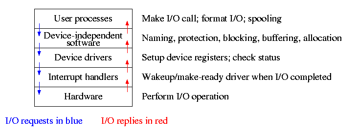
Layers of abstraction as usual prove to be effective. Most systems are believed to use the following layers (but for many systems, the OS code is not available for inspection).
- User level I/O routines.
- Device independent I/O software.
- Device drivers.
- Interrupt handlers.
We will give a bottom up explanation.
5.3.1: Interrupt Handlers
We discussed an interrupt handler before when studying page faults. Then it was called ``assembly language code''.
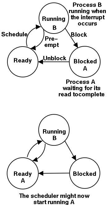
In the present case, we have a process blocked on I/O and the I/O event has just completed. So the goal is to make the process ready. Possible methods are.
- Releasing a semaphore on which the process is waiting.
- Sending a message to the process.
- Inserting the process table entry onto the ready list.
Once the process is ready, it is up to the scheduler to decide when it should run.
5.3.2: Device Drivers
The portion of the OS that ``knows'' the characteristics of the controller.
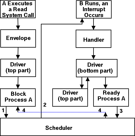
The driver has two ``parts'' corresponding to its two access points. Recall the following figure from the beginning of the course.
- Accessed by the main line OS via the envelope in response to an I/O system call. The portion of the driver accessed in this way is sometimes call the ``top'' part.
- Accessed by the interrupt handler when the I/O completes (this completion is signaled by an interrupt). The portion of the driver accessed in this way is sometimes call the ``bottom'' part.
Tanenbaum describes the actions of the driver assuming it is implemented as a process (which he recommends). I give both that view point and the self-service paradigm in which the driver is invoked by the OS acting in behalf of a user process (more precisely the process shifts into kernel mode).
Driver in a self-service paradigm
- The user (A) issues an I/O system call.
- The main line, machine independent, OS prepares a generic request for the driver and calls (the top part of) the driver.
- If the driver was idle (i.e., the controller was idle), the driver writes device registers on the controller ending with a command for the controller to begin the actual I/O.
- If the controller was busy (doing work the driver gave it previously), the driver simply queues the current request (the driver dequeues this request below).
- The driver jumps to the scheduler indicating that the current process should be blocked.
- The scheduler blocks A and runs (say) B.
- B starts running.
- An interrupt arrives (i.e., an I/O has been completed).
- The interrupt handler invokes (the bottom part of) the driver.
- The driver informs the main line perhaps passing data and surely passing status (error, OK).
- The top part is called to start another I/O if the queue is nonempty. We know the controller is free. Why?
Answer: We just received an interrupt saying so.
- The driver jumps to the scheduler indicating that process A should be made ready.
- The scheduler picks a ready process to run. Assume it picks A.
- A resumes in the driver, which returns to the main line, which returns to the user code.
Driver as a process (Tanenbaum) (less detailed than above)
- The user issues an I/O request. The main line OS prepares a generic request (e.g. read, not read using Buslogic BT-958 SCSI controller) for the driver and the driver is awakened (perhaps a message is sent to the driver to do both jobs).
- The driver wakes up.
- If the driver was idle (i.e., the controller is idle), the driver writes device registers on the controller ending with a command for the controller to begin the actual I/O.
- If the controller is busy (doing work the driver gave it), the driver simply queues the current request (the driver dequeues this below).
- The driver blocks waiting for an interrupt or for more requests.
- The driver wakes up.
- An interrupt arrives (i.e., an I/O has been completed).
- The driver wakes up.
- The driver informs the main line perhaps passing data and surely passing status (error, OK).
- The driver finds the next work item or blocks.
- If the queue of requests is non-empty, dequeue one and proceed as if just received a request from the main line.
- If queue is empty, the driver blocks waiting for an interrupt or a request from the main line.
5.3.3: Device-Independent I/O Software
The device-independent code does most of the functionality, but not necessarily most of the code since there can be many drivers all doing essentially the same thing in slightly different ways due to slightly different controllers.
- Naming. Again an important O/S functionality. Must offer a consistent interface to the device drivers.
- In Unix this is done by associating each device with a (special) file in the /dev directory.
- The i-nodes for these files contain an indication that these are special files and also contain so called major and minor device numbers.
- The major device number gives the number of the driver. (These numbers are rather ad hoc, they correspond to the position of the function pointer to the driver in a table of function pointers.)
- The minor number indicates for which device (e.g., which scsi cdrom drive) the request is intended
- Protection. A wide range of possibilities are actually done in real systems. Including both extreme examples of everything is permitted and nothing is permitted (directly).
- In ms-dos any process can write to any file. Presumably, our offensive nuclear missile launchers do not run dos.
- In IBM and other mainframe OS's, normal processors do not access devices. Indeed the main CPU doesn't issue the I/O requests. Instead an I/O channel is used and the mainline constructs a channel program and tells the channel to invoke it.
- Unix uses normal rwx bits on files in /dev (I don't believe x is used).
- Buffering is necessary since requests come in a size specified by the user and data is delivered in a size specified by the device.
- Enforce exclusive access for non-shared devices like tapes.
5.3.4: User-Space Software
A good deal of I/O code is actually executed in user space. Some is in library routines linked into user programs and some is in daemon processes.
- Some library routines are trivial and just move their arguments into the correct place (e.g., a specific register) and then issue a trap to the correct system call to do the real work.
- Some, notably standard I/O (stdio) in Unix, are definitely not trivial. For example consider the formatting of floating point numbers done in printf and the reverse operation done in scanf.
- Printing to a local printer is often performed in part by a regular program (lpr in Unix) and part by a daemon (lpd in Unix). The daemon might be started when the system boots or might be started on demand. I guess it is called a daemon because it is not under the control of any user. A student has suggested that the usage comes from the meaning of daemon in Greek mythology, namely a guardian spirit. Does anyone know the reason.
- Printing uses spooling, i.e., the file to be printed is copied somewhere by lpr and then the daemon works with this copy. Mail uses a similar technique (but generally it is called queuing, not spooling).
5.4: Disks
The ideal storage device is
- Fast
- Big (in capacity)
- Cheap
- Impossible
Disks are big and cheap, but slow.
5.4.1: Disk Hardware
Show a real disk opened up and illustrate the components
- Platter
- Surface
- Head
- Track
- Sector
- Cylinder
- Seek time
- Rotational latency
- Transfer rate
Overlapping I/O operations is important. Many controllers can do overlapped seeks, i.e. issue a seek to one disk while another is already seeking.
Modern disks cheat and do not have the same number of sectors on outer cylinders as on inner one. However, the disks have electronics and software (firmware) that hides the cheat and gives the illusion of the same number of sectors on all cylinders.
(Unofficial) Despite what tanenbaum says later, it is not true that when one head is reading from cylinder C, all the heads can read from cylinder C with no penalty. It is, however, true that the penalty is very small.
Choice of block size
- We discussed this before when studying page size.
- Current commodity disk characteristics (not for laptops) result in about 15ms to transfer the first byte and 10K bytes per ms for subsequent bytes (if contiguous).
- Rotation rate is 5400, 7600, or 10,000 RPM (15K just now available).
- Recall that 6000 RPM is 100 rev/sec or one rev per 10ms. So half a rev (the average time for to rotate to a given point) is 5ms.
- Transfer rates around 10MB/sec = 10KB/ms.
- Seek time around 10ms.
- This favors large blocks, 100KB or more.
- But the internal fragmentation would be severe since many files are small.
- Multiple block sizes have been tried as have techniques to try to have consecutive blocks of a given file near each other.
- Typical block sizes are 4KB-8KB.
Homework: Consider a disk with an average seek time of 10ms, an average rotational latency of 5ms, and a transfer rate of 10MB/sec.
- If the block size is 1KB, how long would it take to read a block?
- If the block size is 100KB, how long would it take to read a block?
- If the goal is to read 1K, a 1KB block size is better as the remaining 99KB are wasted. If the goal is to read 100KB, the 100KB block size is better since the 1KB block size needs 100 seeks and 100 rotational latencies. What is the minimum size request for which a disk with a 100KB block size would complete faster than one with a 1KB block size?
RAID (Redundant Array of Inexpensive Disks) (Skipped)
- The name RAID is from Berkeley.
- IBM changed the name to Redundant Array of Independent Disks. I wonder why?
- A simple form is mirroring, where two disks contain the same data.
- Another simple form is striping (interleaving) where consecutive blocks are spread across multiple disks. This helps bandwidth, but is not redundant. Thus it shouldn't be called RAID, but it sometimes is.
- One of the normal RAID methods is to have N (say 4) data disks and one parity disk. Data is striped across the data disks and the bitwise parity of these sectors is written in the corresponding sector of the parity disk.
- On a read if the block is bad (e.g., if the entire disk is bad or even missing), the system automatically reads the other blocks in the stripe and the parity block in the stripe. Then the missing block is just the bitwise exclusive or of all these blocks.
- For reads this is very good. The failure free case has no penalty (beyond the space overhead of the parity disk). The error case requires N+1 (say 5) reads.
- A serious concern is the small write problem. Writing a sector requires 4 I/O. Read the old data sector, compute the change, read the parity, compute the new parity, write the new parity and the new data sector. Hence one sector I/O became 4, which is a 300% penalty.
- Writing a full stripe is not bad. Compute the parity of the N (say 4) data sectors to be written and then write the data sectors and the parity sector. Thus 4 sector I/Os become 5, which is only a 25% penalty and is smaller for larger N, i.e., larger stripes.
- A variation is to rotate the parity. That is, for some stripes disk 1 has the parity, for others disk 2, etc. The purpose is to not have a single parity disk since that disk is needed for all small writes and could become a point of contention.
5.4.2: Disk Formatting
Skipped.
5.4.3: Disk Arm Scheduling Algorithms
There are three components to disk response time: seek, rotational latency, and transfer time. Disk arm scheduling is concerned with minimizing seek time by reordering the requests.
These algorithms are relevant only if there are several I/O requests pending. For many PCs this is not the case. For most commercial applications, I/O is crucial and there are often many requests pending.
- FCFS (First Come First Served): Simple but has long delays.
- Pick: Same as FCFS but pick up requests for cylinders that are passed on the way to the next FCFS request.
- SSTF or SSF (Shortest Seek (Time) First): Greedy algorithm. Can starve requests for outer cylinders and almost always favors middle requests.
- Scan (Look, Elevator): The method used by an old fashioned jukebox (remember ``Happy Days'') and by elevators. The disk arm proceeds in one direction picking up all requests until there are no more requests in this direction at which point it goes back the other direction. This favors requests in the middle, but can't starve any requests.
- C-Scan (C-look, Circular Scan/Look): Similar to Scan but only service requests when moving in one direction. When going in the other direction, go directly to the furthest away request. This doesn't favor any spot on the disk. Indeed, it treats the cylinders as though they were a clock, i.e. after the highest numbered cylinder comes cylinder 0.
- N-step Scan: This is what the natural implementation of Scan gives.
- While the disk is servicing a Scan direction, the controller gathers up new requests and sorts them.
- At the end of the current sweep, the new list becomes the next sweep.
Minimizing Rotational Latency
Use Scan based on sector numbers not cylinder number. For rotational latency Scan which is the same as C-Scan. Why?
Ans: Because the disk only rotates in one direction.
Homework: 24, 25
5.4.4: Error Handling
Disks error rates have dropped in recent years. Moreover, bad block forwarding is normally done by the controller (or disk electronic) so this topic is no longer as important for OS.
5.5: Clocks
Also called timers.
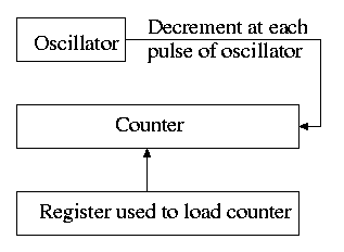
5.5.1: Clock Hardware
- Generates an interrupt when timer goes to zero
- Counter reload can be automatic or under software (OS) control.
- If done automatically, the interrupt occurs periodically and thus is perfect for generating a clock interrupt at a fixed period.
5.5.2: Clock Software
- TOD: Bump a counter each tick (clock interupt). If counter is only 32 bits must worry about overflow so keep two counters: low order and high order.
- Time quantum for RR: Decrement a counter at each tick. The quantum expires when counter is zero. Load this counter when the scheduler runs a process.
- Accounting: At each tick, bump a counter in the process table entry for the currently running process.
- Alarm system call and system alarms:
- Users can request an alarm at some future time.
- The system also on occasion needs to schedule some of its own activities to occur at specific times in the future (e.g. turn off the floppy motor).
- The conceptually simplest solution is to have one timer for each event.
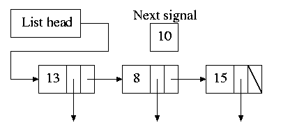
- Instead, we simulate many timers with just one.
- The data structure on the right works well.
- The time in each list entry is the time after the preceding entry that this entry's alarm is to ring.
- For example, if the time is zero, this event occurs at the same time as the previous event.
- The other entry is a pointer to the action to perform.
- At each tick, decrement next-signal.
- When next-signal goes to zero, process the first entry on the list and any others following immediately after with a time of zero (which means they are to be simultaneous with this alarm). Then set next-signal to the value in the next alarm.
- Profiling
- Want a histogram giving how much time was spent in each 1KB (say) block of code.
- At each tick check the PC and bump the appropriate counter.
- A user-mode program can determine the software module associated with each 1K block.
- If we use finer granularity (say 10B instead of 1KB), we get increased accuracy but more memory overhead.
Homework: 27
5.6: Character-Oriented Terminals
5.6.1: RS-232 Terminal Hardware
Quite dated. It is true that modern systems can communicate to a hardwired ascii terminal, but most don't. Serial ports are used, but they are normally connected to modems and then some protocol (SLIP, PPP) is used not just a stream of ascii characters. So skip this section.
Memory-Mapped Terminals
Not as dated as the previous section but it still discusses the character not graphics interface.
- Today, software writes into video memory the bits that are to be put on the screen and then the graphics controller converts these bits to analog signals for the monitor (actually laptop displays and some modern monitors are digital).
- But it is much more complicated than this. The graphics controllers can do a great deal of video themselves (like filling).
- This is a subject that would take many lectures to do well.
- I believe some of this is covered in 201.
Keyboards
Tanenbaum description of keyboards is correct.
- At each key press and key release a code is written into the keyboard controller and the computer is interrupted.
- By remembering which keys have been depressed and not released the software can determine Cntl-A, Shift-B, etc.
5.6.2: Input Software
- We are just looking at keyboard input. Once again graphics is too involved to be treated here.
- There are two fundamental modes of input, sometimes called raw and cooked.
- In raw mode the application sees every ``character'' the user types. Indeed, raw mode is character oriented.
- All the OS does is convert the keyboard ``scan codes'' to ``characters'' and and pass these characters to the application.
- Some examples
- down-cntl down-x up-x up-cntl is converted to cntl-x
- down-cntl up-cntl down-x up-x is converted to x
- down-cntl down-x up-cntl up-x is converted to cntl-x (I just tried it to be sure).
- down-x down-cntl up-x up-cntl is converted to x
- Full screen editors use this mode.
- Cooked mode is line oriented. The OS delivers lines to the application program.
- Special characters are interpreted as editing characters (erase-previous-character, erase-previous-word, kill-line, etc).
- Erased characters are not seen by the application but are erased by the keyboard driver.
- Need an escape character so that the editing characters can be passed to the application if desired.
- The cooked characters must be echoed (what should one do if the application is also generating output at this time?)
- The (possibly cooked) characters must be buffered until the application issues a read (and an end-of-line EOL has been received for cooked mode).
5.6.3: Output Software
Again too dated and the truth is too complicated to deal with in a few minutes.
5.7: Graphical User Interfaces (GUIs)
Skipped.
5.8: Network Terminals
Skipped.
5.9: Power Management
Skipped.
5.10: Research on Input/Output
Skipped.
5.11: Summary
Read.
 Ctrl+M
No comments:
Post a Comment